A pressure switch is a device that can be used to detect the water pressure in a tank and operate the pump motor if the pressure is too low or if the water in the tank falls below the required minimum level.
Before we discuss the proposed tank pressure controller circuit diagram, it is important to understand how a pressure switch works.
It is actually a simple electromechanical device that connects internal electrical contacts when the water pressure at the pressure nozzle exceeds a preset point. When the pressure drops below another specified lower preset point, the internal contact releases or disconnects.
Optimising tank pressure using pressure switches
The pressure switches described above can be effectively applied to the specified requirements. The following narration describes the entire process.
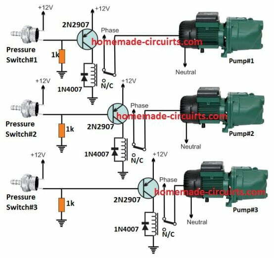
The water supply circuit required for a flat with constant pressure can be visualised in the diagram below:
It meets the main requirement of optimising the water supply pressure at a constant rate by switching on additional pumps sequentially during periods of low water pressure and vice versa.

Referring to the diagram, we can see 3 identical stages where the 3 pressure switches are configured with 3 associated relay driver stages with relay contacts connected to the corresponding 3 pumps.
In the relay driver stage, we use PNP transistors because the pressure switch response is normally closed during low pressure and opens when the pressure reaches the maximum threshold level.
This means that the pressure unit’s internal switches remain unconnected or closed when the pressure is low. This allows the pnp transistor to conduct through a ground biased 1 k resistor. The relay also opens and starts the motor. All 3
motor pump stages have the same basic operation.
Now, on request, assume that the pressure is very low, which causes all 3 pressure switches to open their internal contacts.
As a result, all 3 motorised pumps switch on together. As a result, the water supply pressure climbs quickly and reaches the required optimum point, which causes pressure switch 3 and pressure 2 to open. As a result, this switches off the connected motorised pumps No. 3 and No. 2.
Motorised pumps No. 3 and No. 2 are switched off.
At this point, only motor 1 handles the water supply to the flat.
If there is a sudden increase in the demand for water in the building, this results in a drop in the water pressure, so that motor pump #1 alone is not sufficient to meet the demand.
This situation triggers pressure switch #2 to operate, which starts motorised pump #2 to help meet the high water pressure demand required.
However, if water usage continues to increase and the first 2 pumps are still unable to meet the demand, pressure switch #3 detects this and activates motorised pump #3.
The sequential switching ON/OFF of the above pumps responds to changes in tank pressure to meet the main basic requirements.
Electric Pump Switching
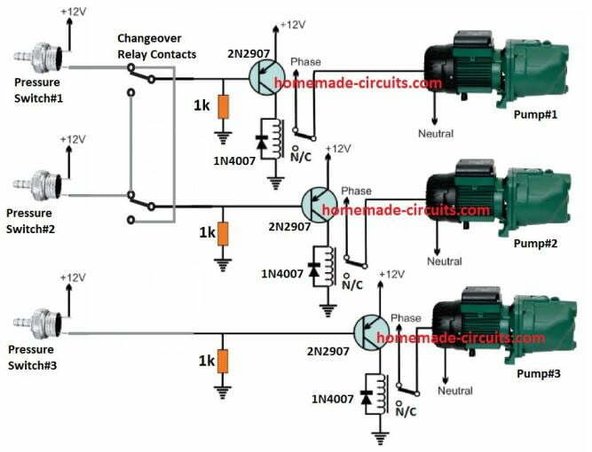
The second requirement is that the pumps shuffle into each other so as to relieve most of the open operating pressure on motor pump 2 from time to time by sharing the load with motor 1.
This ensures that the working life of the motor is extended by reducing its wear effect.

The diagram above demonstrates how this can be achieved with a simple conversion DPDT relay connected between the relevant pressure switch and relay driver stage.
In this concept, only two motors are considered for switching and a third motor is not included to avoid design complexity In addition, the two motors sharing seems to be sufficient to keep their wear below unsafe levels.
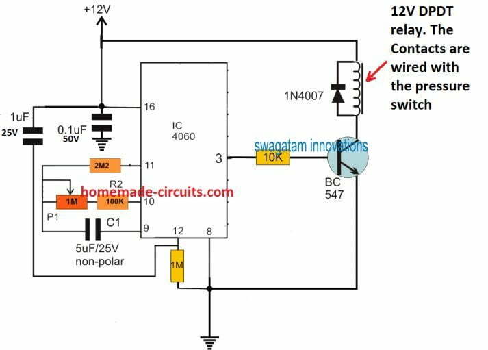
The changeover relay performs one basic job. It alternately switches the motor #1 and motor #2 relay drivers on pressure switches #1 and #2. The time at which each motor engages the pressurised water supply is determined by a simple IC
4060 timer as shown below:

The time delay for initiating the transition can be set by properly adjusting the 1 M potentiometer. Through some trial and error, the potentiometer resistor can be replaced with a fixed value resistor.
Power for all electronic stages is available from a standard 12 V 1 A adapter.
All relays are 12 V 30 A relays.
